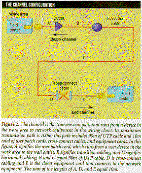
Labels:text | screenshot | font | diagram | parallel | number | line OCR: THE CHANNEL CONFIGURATION Work area Field tester Figure 2. The channel is the transmission path that riss from a device in the work aren to network equipment in the wiring closet. Its maximiem transmission path is 100m; this path inchides 90m of UITP cable and 10m total of user patch cord ,, cross-connect cables, and equipment cards. In this figure. A signifies the user patch cord, which runs from a user device in the swirk oren to the wall outlet. B signifies transition cabling, and C signifies horizontal cabling: B and C equal Som of UIP cable, 1) is cross-connect cabling and E is the closet equipment cord that connects to the network epeipment. The sum of the lengthis of A. D. and E equal 10m.